Tuesday, December 7, 2021

UL20789 cable

UL20789 is a 105degC, 30 Volts cable. 

The minimum conductor is 40AWG. 

As UL20789 is able to use smaller gauge conductors as small as 40awg, it may use for the below application:-  

DVD, CD-ROM, P-PDVD, LCD, LCD TV, Digital Camera, Laptop, Equipment, Printer, Scanner, Learning Machine and etc..

The below specification is currently Pan-International provided for Car Audio.


Universal Serial Bus (USB) 2.0

Universal Serial Bus (USB) 2.0 is an external interface used on computers and other digital devices to transfer data through a cable. The designation “2.0” refers to the standard or version of the interface and it was released in 2000. While USB 3.0 was made standard in 2008, it is backward compatible with older versions. The primary difference between each version has been a major increase in transfer rates, with USB 2.0 improving upon the original release and 3.0 being even faster.

Major Features

USB is a plug-and-play interface, which means that a computer does not need to be powered off in order to plug in or unplug a component. For example, a media player can be connected to a computer via a USB while the machine is still in use, making these devices "hot swappable." The computer registers the device as another storage area and shows any files it contains. Other types of ports often require that someone shut down a computer before making such a connection, which led to much of the format's popularity.

The maximum approved length for a USB 2.0 cable is about 16 feet (5 meters). This limitation is based on how quickly a signal travels through the cable. If it takes too long, then the connected devices indicate that it was lost, and anything over about 16 feet (5 meters) exceeds this time.

Upgrade From 1.0

When USB standards change from an existing version to a newer version, as they did from 1.1 to USB 2.0, the major improvement is often the speed at which data transfers between connected devices. In 1.0 and 1.1, there were two speeds available: "low speed" with a rate of 1.5 megabits per second (Mbit/s) and "full speed" at 12 Mbit/s. USB 2.0 improved upon these with "hi-speed" transfer rates of 480 Mbit/s. Since this standard is typically backward compatible, the 2.0 version includes the older "full speed" and "low speed" rates to function with 1.0 devices.

Even in USB 2.0, "low speed" was often used for data transfers between a computer and a mouse or keyboard, except for high-end gaming devices. Memory sticks and external hard drives became much more powerful with the 2.0 standards, since they often ran into "bottlenecks" with older transfer rates. A bottleneck is a point at which data is slowed down by limitations in transfer rate, such as the slower speeds of 1.0 ports, even though the devices themselves can send and receive data much faster.

Common Devices

Aside from media players, many other external devices use these data ports, including digital cameras, mobile phones, and newer cable boxes. Native components also make use of this interface, such as mice, keyboards, and external hard drives, as well as printers and networking hardware. One of the most popular and convenient USB 2.0 gadgets is a memory stick, which can store data for easy transfer between machines.


Introduction of 3.0

In 2008, USB 3.0 was officially adopted as the new standard for this format. It introduced new connections that included more pins, allowing for "SuperSpeed" data transfer rates of up to 5 gigabits per second (Gbit/s). The 3.0 standard maintained backward compatibility, including "hi-speed" and "full speed" rates to function with older USB 2.0 devices.


Wednesday, January 6, 2021

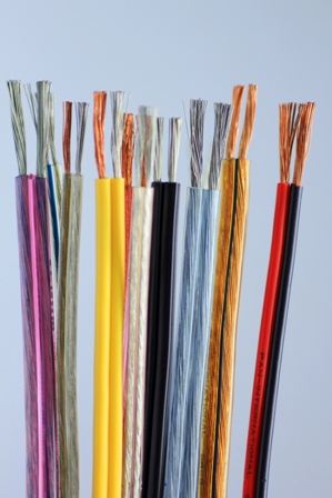
AWM UL 2468 Specification of Speaker Wire

Speaker wire is used to make the electrical connection between loudspeakers and audio amplifiers. modern Speaker wire consists of two electrical conductors individually insulated by plastic. Certain older designs also featured another pair of wires for a powered line to power an electromagnet in the loudspeaker before permanent magnets became economical to produce and use.The effect of Speaker wire upon the signal it carries has been a much-debated topic in the audiophile and high fidelity worlds.

Speaker wire, like any other linear electrical component, has three parameters which determine its performance: resistance, capacitance, and inductance. If a perfect wire were possible, it would have no resistance, no capacitance, and no inductance. The shorter a wire is, the closer it comes to being perfect, as resistance decreases as length decreases in all conductors (except superconductors).

Resistance is the property which has the most effect on speaker wire performance, whereas capacitative and inductive characteristics of speaker wire are insignificantly small relative to the loudspeaker itself. Larger conductors (smaller wire gauge) have smaller resistance. As long as speaker wire resistance is kept to less than 5% of the speaker's impedance, the conductor will be adequate for home use.

Steranded speaker wire is more flexible than solid wire, and is suitable for movable equipment. Even with poor-quality wire, an audible degradation of sound may not exist. Many supposedly audible differences in speaker wire can be attributed to listener bias or the placebo effect.

Below is the Specification commonly use for speaker.

UL2468 22AWG 2F Cable.
wp394


SPECIFICATION OF APPLIANCE WIRING MATERIAL (AWM)
                                                                                                       

1.0           SCOPE
                For Internal Wiring of Electronic or Audio Appliances

2.0           TYPE AND RATING
2.1           Type                                       : AWM 2468 & AWM IA
2.2           Rating Temperature                : 80º C
2.3           Rated Voltage                          : 300 Volts
                                                                  
3.0           CONSTRUCTION

3.1           CONDUCTOR
3.1.1        Material                                  : Bare Annealed Copper Wire (SBR)
3.1.2        Diameter of Conductor           : 0.160mm ± 0.005mm
3.1.3        Construction                           : 22AWG or 17/0.16 mm       

3.2           INSULATION
3.2.1        Material                  : Polyvinyl Chloride (PVC)
3.2.2        Average Thickness  : 0.38mm
3.2.3        Min Thickness        : 0.33mm
3.2.4        Overall Diameter     : 1.70mm ± 0.15mm * 3.5mm ± 0.20mm
3.2.5        Colour                     : As per Request

4.0           PHYSYCAL PROPERTIES
4.1.1        Oven Aging                             : 168 hours at 113º C
                After Aging                             : Elongation                             : 65% of unaged
                                                                : Tensile Strength                    : 70% of unaged
4.1.2        Deformation Test   : 1 hour at 121º C
                After test                                : 50% of before
4.1.3        Cold Bend Test       : 1 hour at -10º C
                After test                                : Not show any surface Cracks
4.1.4        Flame Test              : VW-1 & FT-1 as UL & c(UL) request

4.1.5        Spark Test              : 4 KV

5.0           PACKING
                Length                                     : 610M

-----------------------------------------------------------------------------------------------------

Tuesday, January 5, 2021

 XLPE - cross-linked polyethylene

XLPE is an abbreviated designation of “cross-linked polyethylene”. Polyethylene has a linear molecular structure as shown in A. Molecules of polyethylene not chemically bonded as shown in B are easily deformed at high temperature, while XLPE molecules bonded in a three dimensional network as shown in C and D, have strong resistance to deformation even at high temperature.

Cross linked polyethylene is produced from polyethylene under high pressure with organic peroxides as additives. The application of heat and pressure is used to effect the cross linking. This causes the individual molecular chains to link with one another which in turn causes the material to change from a thermoplastic to an elastic material.

An important advantage of XLPE as insulation for medium and high voltage cables is their low dielectric loss. The dielectric loss factor is about one decimal power lower than that of paper insulated cables and about two decimal powers lower than that of PVC-insulated cables. Since the dielectric constant is also more favourable, the mutual capacitance of XLPE cables is also lower, thus reducing the charging currents and earth-leakage currents in networks without the rigid star-point earthing.


“XLPE” Insulation Offers These Advantages:

·                  Outstanding physical and mechanical toughness

·                  Extremely low moisture absorption

·                  Excellent ozone resistance

·                  Strong resistance to chemicals fumes and gases

·                  Low SIC and power factor

·                  High impulsed strength

·                  High insulation resistance and dielectric strength

·                  Capability of carrying and terminating

·                  Easy to splicing and terminating


Below is commonly use UL Style for XLPE insulated hook up wire.

UL3386    105ºC 600V XLPE INSULATED WIRE
Halogen Free


·                 Rated temperature:105ºC·                 

·               Rated voltage: 600v

·                 According to:UL subject 758, UL1581, CSA C22.2

·                 Solid or Stranded, Tinned or bare copper conductor 32~8AWG

·                 XLPE insulation

·                 Passes UL VW-1 & CSA FT1 Vertical flame test

·                 Uniform insulation thickness of wire to ensure easy stripping and cutting.

·                 RoHS Compliant.

·                 UL3386 wire can use for the Internal wiring of appliances where exposed to oil at a temperature not exceeding (60°C or 80°C, whichever is applicable).


Gauge(AWG)

Copper (mm)

Conductor OD (mm)

insulation thickness

(mm)

wire O.D

(mm)

Max Cond. resistanceΩ/kft ,20ºC

26

7/0.16

0.48

0.76

  2.10±0.1

45.2

24

11/0.16

0.61

  2.25±0.1

29.3

22

17/0.16

0.76

  2.35±0.1

16.7

20

21/0.178

0.94

  2.55±0.1

10.5

18

16/0.254

1.16

  2.80±0.1

6.52

16

26/0.254

1.49

  3.10±0.1

4.18

14

41/0.254

1.87

  3.77±0.1

2.62

12

65/0.254

2.36

  4.14±0.1

1.65

10

105/0.254

3

  5.20±0.1

1.04

8

119/0.3

4.25

1.14

  6.90±0.2

0.653


UL3271 Specification

APPLIANCE WIRING MATERIAL

Subj.758               Section 3      Page 3271                              Issued:1972-08-02

                                                                                              Revised:2011-10-04

 Style 3271  Single conductor with extruded sulation.

Rating

125 deg C, 600 Vac, 750 Vdc, Horizontal flame.

Conductor

30 AWG - 1000 kcmil solid, stranded, or braided, tinned, bare or silver-plated 
copper or solid or stranded coated high strength copper - minimum 90 percent conductivity.

Insulation

Extruded XLPE.

Conductor size

Minimum average thickness

Minimum thickness at any point

30-9 AWG

30 mils

27 mils

8-2 AWG

45 mils

40 mils

1-4/0 AWG

55 mils

50 mils

213-500 kcmil

65 mils

58 mils

501-1000 kcmil

80 mils

72 mils

1001-2000 kcmil

95 mils

86 mils

Standard

Appliance Wiring Material UL 758.

Marking

General.

Use

For use as Motor Leads or Internal Wiring of appliances. Tags may indicate the following: 2500 volt peak - For Electronic Use Only.


Contact : CT Loo